Porcelain Insulator News
by Elton Gish
Reprinted from "Crown Jewels of the Wire", November 1999, page 13
Patrick McNabb (NIA #6643) and his wife Mary Ellen (NIA #6644) visited with
me earlier in the year. They had a very unusual fuse cutout (also called fuse
holder) made of unglazed white dry process porcelain. Sure we have all seen fuse
cutouts from time to time but I'll bet you haven't seen one like this. The
bottom is nearly 4" square and the overall height is 5-3/4". It is
missing the porcelain knife blade that holds the fuse wire and slips inside the
bottom to complete the electrical circuit. Note the rather prominent recess-embossed marking. The complete marking is:
PERU / PATENTED / DEC. 14 1897
A fuse cutout was mounted on a crossarm with bolts passing through the two
holes. A wire fuse was wrapped up and over the knife blade or plug that was
inserted inside the outer shell. The knife had a knob on the lower end that
acted as a handle. The knife could be pulled out with a long hand-held pole
without climbing leaving the ground. The fuse holder was used to protect a
transformer (mounted on the same pole) from lightning and other power surges.
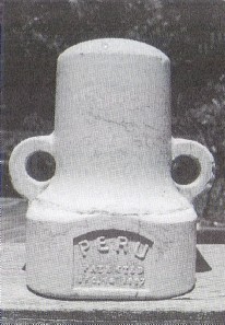
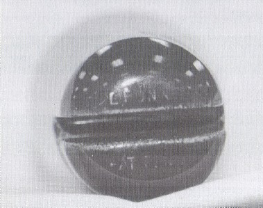
Front view of a Peru fuse holder
with 1897 patent date.
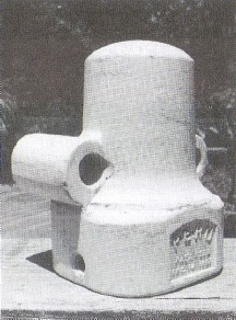
A second view of a Peru fuse holder
with 1897 patent date.
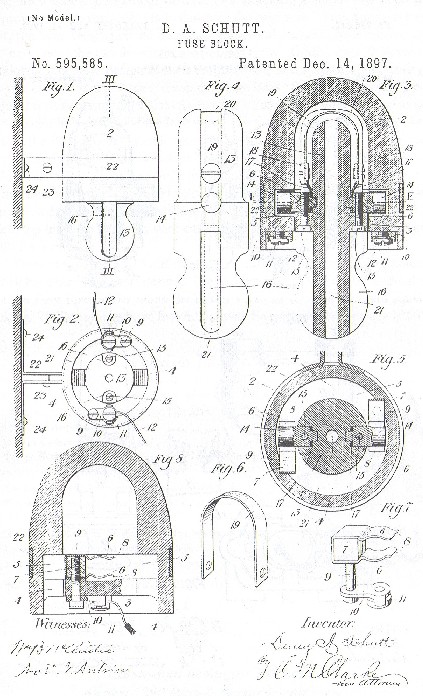
Patrick's insulator is the earliest known example of a fuse cutout. Bob Stahr
(NIA #4186) generously looked up the patent number for me so I could order a
copy of the patent. Duny Schutt was granted patent No. 595,585 on
December 14,
1897. The patent was assigned to the Peru Electric Manufacturing Co. of Peru,
IN. (See following page for patent.) Note that the patent drawing does not look
anything like the actual fuse holder but the basic idea is accurately shown. It
is not uncommon for actual specimens to vary from the patent drawing. However,
Peru apparently did manufacture a fuse holder that matched very close to the
patent drawing. The January 1899 issue of "The Buyers' Reference"
shows an illustration of a Peru "All Porcelain Transformer Fuse Box"
that is very similar to the patent drawing. Note that it was mounted on the
crossarm with a sheet metal bracket. Peru may have changed the design of the
"fuse box" so it could be mounted more securely with two bolts.
Patents are good for 17 years so we can assume Patrick's fuse cutout was made
sometime between 1899 and 1914. It is possible that Peru applied for a patent
for the different mounting.
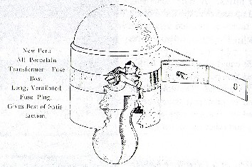
Illustration from the January 1899 issue
of "The Buyers' Reference"

James Wood (Ft. Wayne, IN) obtained patent No. 736,049 on August 11, 1903 for
a similar fuse cutout with the two mounting holes as well as certain
improvements in the knife blade that held the fuse wire. This design is
basically the same design that industry used for several decades. Note the two
lugs or "ears" near the top for securing the lead wires. Oddly, Pass
& Seymour cataloged this basic design in their August 1899 and August 1900
catalogs. As you can see in the catalog illustration, the P&S
"Porcelain Junction Box" utilized the two mounting holes like
Patrick's Peru fuse holder and it also had two smaller holes to tie-off the lead
wire. The internals were essentially identical to the Wood patent granted four
years after the P&S catalog. I have seen an unglazed white P&S fuse
holder but I do not recall if it had the two tie-off holes near the top. Note
that the September 1911 P&S catalog referred to it as a "transformer
cutout", and the two holes on the top have been enlarged. Two somewhat
different styles were illustrated. The earliest style has a more cylindrical top
half like Patrick's Peru cutout and the ones shown in the 1899 and 1900 P&S
catalogs.
There are at least 12-15 different styles and manufacturers off use
holders but all have the same basic design. The earliest models had a tall
narrow shell like the Peru fuse holder while the newer versions were shorter and
squatty looking. I believe this type of fuse holder was discontinued in the early
1950's.
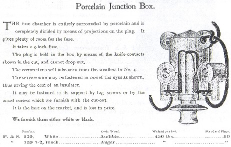
Illustration in August 1899 and
August 1900 Pass & Seymour catalogs.

Two styles of transformer fuse cutouts shown in the
September 1911 Pass &
Seymour catalog.
The next insulator is one of a very few styles known as "patent
top" insulators. The intent of these various patented designs was to
eliminate the use of the tie-wire. Installing the tie-wire was the most time
consuming part of stringing a line along miles of insulators. The conductor wire
had to be secured to the insulator and the most effective way was to apply a
tie-wire. From 1869 to 1941 at least 135 patents were granted for various
ingenious methods to eliminate the use of the tie-wire with all but two granted
before 1927. The various self-tying insulator patents can be grouped in several
general categories such as "slot-top" (U-185 Slusser patent and U-187
Pierce patent), "screw-top" (U-181 Bell patent), and
"twist-lock" (U-183 Ranson patent, U-184 Harloe patent, and U-186
Purkey patent). U-182A/B (Prenzel patent) is a different design where the
conductor is clamped between the top half and bottom half in pre-formed slots
for a specific wire gauge by screwing the top half of the insulator down on the
pin.
Rick Soller (NIA #2958) was the first to report the new
"twist-lock" insulator that I assigned U-183A. Rick said he obtained
the insulator from an employee of Square D. From 1925 to 1951 the Square D Co.
manufactured dry process pin-type insulators at their factory in Peru, IN.
Rick's U-183A is unmarked and was finely made of dry process porcelain. The pinhole
is unconventional in that, instead of threads, it has an intricate set of
grooves formed in the smooth pinhole to secure and lock the insulator on
specially designed pin. No examples of the pin have been found.

Jeff Hogan
reported a second U-183A owned by Dan Raber. Dan showed it around earlier this
year at the Huntsville show and recently at the Crown Point Regional NIA show.
Dan's insulator is identical to Rick's U-183A in every way except Dan's
insulator has an embossed marking (typical on dry process porcelain) on the top
on either side of the slot. The marking reads: L. FUNK / PAT PEND Rick's
insulator has a penciled notation inside it which he now interprets to be
"L. Funk".
No one has found a patent granted to L. Funk. I even
searched through Jack Tod's extensive patent research notes for the years Square
D was in operation. We know the insulator was produced at least in limited
quantities so Square D did work out the problem of forming the intricate grooves
and slots in the pinhole and the vertical and horizontal slots in the top.

Rick Soller's photos of his U-183A: Note the
intricate grooves in the
unglazed pinhole.
 |
Note the opening for the conductor wire through the horizontal groove when
U-183A is twisted 90 degrees to lock the wire in place effectively eliminating
the need for a tie-wire. |
Since
apparently no patent was granted, Square D could have abandoned the patent application
due to lack of interest or expense to produce. Various factors such as the
Depression, cost to produce, little interest from utility companies, WorId War
II, introduction of high frequency carrier circuits, and the replacement of open
communication lines with cable could have contributed to the "failure"
of this design. Remember that nearly all of the patents for these special tie-less insulators were granted before 1927. We do not know when the patent
application was filed but it probably was during the earlier years of Square D
and most likely before 1930. I suspect that the design was too complicated for
utility customers to consider changing out both the insulator and pin on their
existing lines.

Dan Raber's U-183 (photo courtesy of Jeff Hogan):
Note the fully glazed
pinhole.
Dan Raber's U-183 (photo courtesy of Jeff Hogan) showing
embossed marking on
top: L. FUNK / PAT PEND
The insulator could have been used as a replacement on existing
lines by changing out the pin. The existing conductor was dropped in the top
slot in U-183A and the insulator twisted 90 degrees to lock the conductor in the
horizontal groove. Since we do not have the patent or patent application to help
us understand how the slotted pinhole worked, we can only make a guess. It is
not obvious in the drawing I made of U-183A, but the slots in the pinhole are
curved around the inside of the pinhole. Apparently a large diameter hollow,
round metal pin was used that had two horizontal knobs or projections on
opposite sides of the pin. These projections would fit in the short vertical
slots (180 degrees apart) in the pinhole, travel along the horizontal slot when
the insulator was twisted 90 degrees, and slide up vertically locking in the
short upper horizontal slot. The only difference between the two U-183A's is the
pinhole in Rick's insulator is unglazed and the pinhole in Dan's insulator is
fully glazed with only the bottom firing rest unglazed.
| 
)
)
)
)
)
)
)
)
)
)
)
)